


Head light and Horn Installation with Abbreviated Wiring Loom
By Matt Roessle (MattR)
March 04, 2006
When I purchased my 2001 GasGas XC250, the bike already came with an abbreviated wiring loom. Compared to the EC250 with full accessories, my bike had a head light with low beam only, a tail light, brake light, and kill button. In order to make my bike street legal in Michigan, I needed a head light capable of high and low beam modes along with a horn. The nice thing about the stock head light was the bulb already had terminals for the high and low beams. Therefore, it was only a matter of making the necessary wiring connections. This tech article discusses the wiring necessary for a high/low/off head light switch and horn using an abbreviated wiring loom.
On my bike, the head light came stock with a toggle switch on the headlight shell. Unfortunately, this toggle switch was a single pole single throw (SPST) and could only be wired for a low beam or high beam mode but not both. Therefore, the first component necessary for my conversion was a double pole double throw (DPDT) toggle switch with a “center off” position. This allowed the head light to operate in low beam, high beam, or off conditions. Since the tail light must function in either low or high beam modes, the double pole switch allowed the tail light to be also properly wired.
A wiring diagram of the complete system is shown below. On the DPDT toggle switch, the center poles (my switch had 2 poles) are to be connected to the source. On one side of the toggle switch, there are 2 poles which provide power to the head light low beam and tail light. On the other side of the toggle switch, there are 2 poles which provide power to the head light high beam and tail light. I recommend soldering the wires to the toggle switch terminals for the best connection. Also, I recommend that all spliced wires should be soldered and have heat-shrink tubing used for protection. Alternatively, crimped-on terminals and connectors can be used.
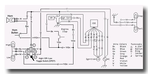
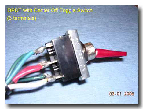
Photo 1 : DPDT toggle switch after wires were soldered to the terminals
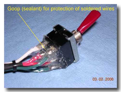
Photo 2 : Goop was used to as a sealant to protect the soldered wires
The second component needed for my conversion was a horn. I used the OE horn that was available from GasGas (made by Leonelli). As shown in Photos 3 and 4, this horn was mounted on the head light shell directly opposite of the toggle switch. The horn had 2 terminals that had to be wired between the source and the handlebar switch for the horn.
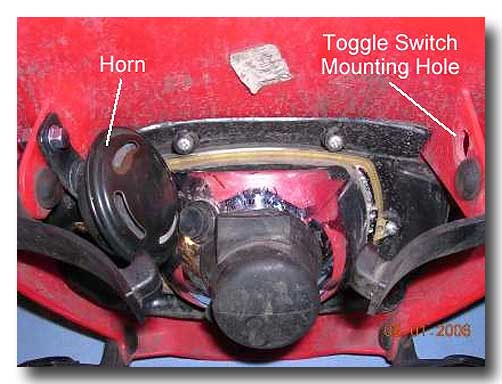
Photo 3 : Horn was mounted on the left side of headlight shell.
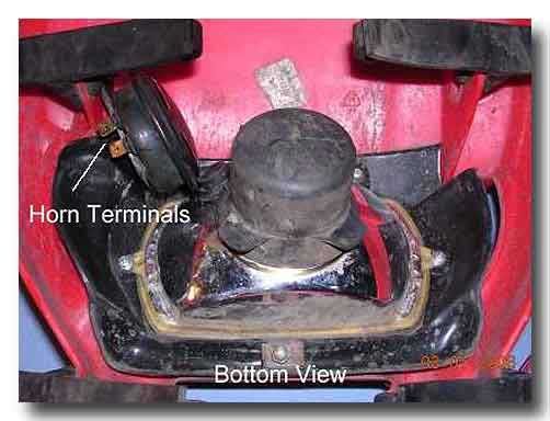
Photo 4 : Bottom view showing the 2 terminals on the horn.
To give my bike a “clean” look, I chose to use a 2-wire kill button to activate the horn. The horn button was mounted on the right side of the handlebar (see Photo 5), whereas, the kill button was mounted on the left side of the handlebar (see Photo 6). Note: I chose the horn button to have a different shape than the kill button. This provides a visual reminder that these buttons serve different functions in case someone else rides my bike (or I forget due to my old age).
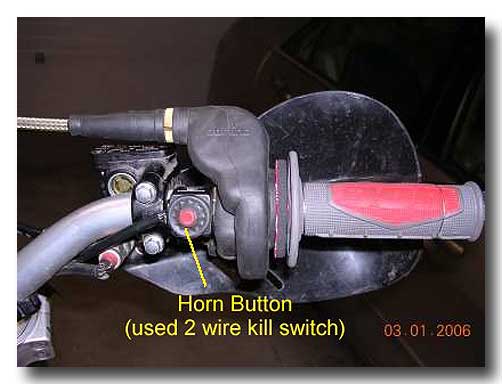
Photo 5 : Horn button located on right side of handlebar.
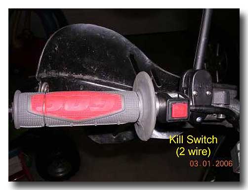
Photo 6 : Kill button located on left side of handlebar.
The third component needed for my conversion was a multiple pin connector to give a “clean” look. As shown in Photos 7 and 8, I chose a 4 pin connector that was available from Radio Shack. In Photo 7, the male terminal connector was for the wires leading to the head light and horn. Pin 1 was for the green wire connected to the horn. Pin 2 was for the violet wire connected to the toggle switch (i.e., power the tail lights). Pin 3 was for the yellow/green wire (ground) connected to the head light bulb terminal. Pin 4 was for the red wires (source) connected to the toggle switch and horn. It should be noted that I had 2 red wires branching off of Pin 4. One red wire was for the head light toggle switch and the other red wire was for the horn.

Photo 7: 4 pin connector (male terminal) for wires leading to the head light and horn.
In Photo 8, the female terminal connector was for the wires leading to the bike. Pin 1 was for the green wire on the horn button (actually my horn button wire was black). Pin 2 was for the violet wire to the rear tail light. Pin 3 was for the yellow/green wire connected to ground on the bike frame. It should be noted that I had 2 wires branching off of Pin 3. One yellow/green wire was for the original ground wire in the bike’s wiring loom and the other yellow/green wire was for the horn button (actually my horn button wire was black with white stripe). Pin 4 was for the yellow wire connected to the bike’s power system (i.e., the source). Note: the yellow wire becomes a red wire in my wiring diagram (see Photo 1).

Photo 8: 4 pin connector (female terminal) for wires leading to the bike.
The completed wiring loom is shown in Photo 9. A close-up view of the head light and horn terminals is shown in Photo 10.
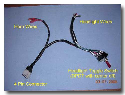
Photo 9: Completed wiring loom for the head light and horn.
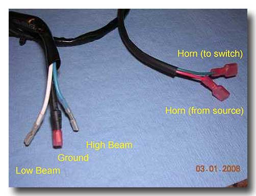
Photo 10: Close-up view of the head light and horn terminals.
With the wiring loom fully completed, the next step was installation of this assembly onto the head light shell. In Photo 11, the relative size of the wiring loom can be compared to the head light shell. As shown in Photo 12, the toggle switch was installed on the right side of the head light shell and all terminals were connected to the head light bulb and horn. It should be noted that on the head light bulb, the left side terminal is for ground (yellow/green wire), the middle terminal is for high beam (blue wire), and the right side terminal is for low beam (white wire). In Photo 13, a close-up view of the toggle switch and head light wiring is provided. In Photo 14, a close-up view of the horn and its wiring is provided. A side view of the head light assembly is shown in Photo 15. It can be seen that all components have a “low profile” appearance and do not stick out beyond the head light bulb. Therefore, there would be no clearance issues with the forks once the head light was mounted onto the bike.
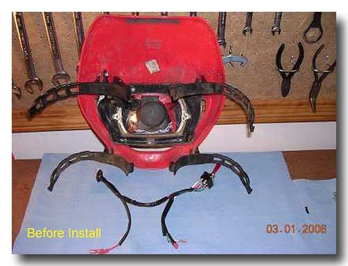
Photo 11: Wiring loom before installation onto head light shell.
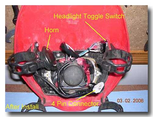
Photo 12: Wiring loom after installation onto head light shell.
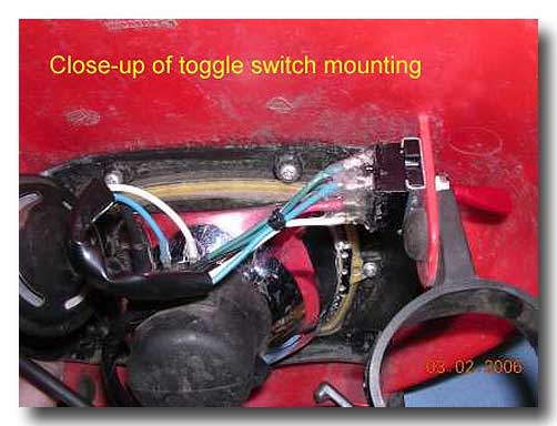
Photo 13: Close-up view of toggle switch and head light wiring.
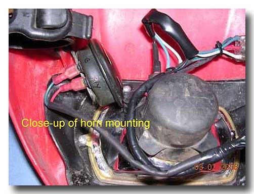
Photo 14: Close-up view of horn and its wiring.
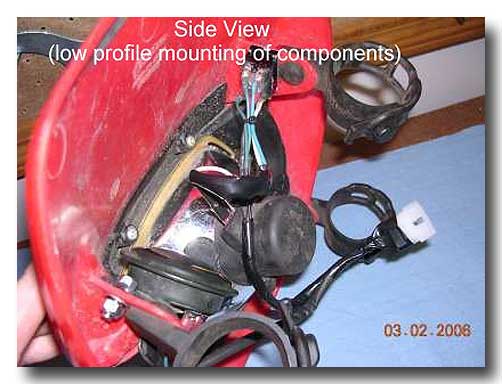
Photo 15: Side view of head light assembly with horn and wiring loom.
Note: all components have a “low profile” do not stick out beyond the head light bulb.
The final step for my conversion project was simply to connect the 4 pin connector and strap the head light assembly to the fork. In Photo 16, the 4 pin connector is shown connected. In Photo 17, my bike is shown after final installation of the head assembly.
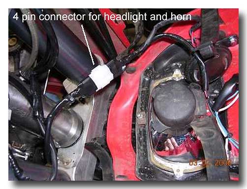
Photo 16: The 4 pin connector makes final installation an easy task.
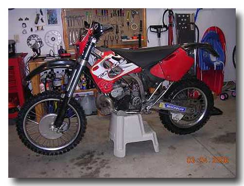
Photo 17: My bike after final installation of the head light assembly.

copyright 2006 - gasgasrider.org